User's Manual for the Versalab Espresso Press compressed air
The Versalab Espresso PRESS will compress the grounds in a espresso filter basket extremely consistently and, if desired, to a much higher pressure than is practical by a person - giving possible improvements in coffee puck behavior.
The PRESS is powered by compressed gas. DO NOT use street gas or propane! Only bottled nitrogen, or CO2. This is easily sourced from a local supplier. It should include a pressure regulator with gauge affixed to the top of the tank. We supply with the PRESS a flow restrictor which allows you to further fine-tune the speed of the Plunger. Compressed air from a tank connected to an air compressor will work fine providing the tank is regularly drained from moisture – a result of the compression of air.
Installation should only be undertaken by someone with the skills and knowledge to do simple plumbing and mechanical work.
Two parts of the PRESS are made to different specifications to suit the particular portafilter. The Plunger is available to suit 58mm and 53mm diameter and VST filter baskets. The Rest is available in three versions: to suit bottomless (or naked) portafilters; double spouted original type LaMarzocco type; or the LaMarzocco open type double spout. Custom sizes of both the Plunger and Rest can be special ordered for an additional cost.
Installation
Typically the PRESS is placed between the grinder and the espresso machine. All but the main body of the PRESS is expected to be under-counter, with three small plastic tubes passing through a hole in the countertop to connect the plumbing, in-line flow restrictor, and gas tank.
The operating valve [on/off switch] comes positioned on the left, but with very little work it can be changed to the right, if desired. See instructions at end.
Hooking up the necessary gas arrangement is relatively straightforward. One option is to use a C10-size tank and regulator (make sure it is a pressure regulator not a flow regulator) of compressed CO2 or nitrogen, such as used for draft beer home use. Obtain these from local suppliers. The regulator on the tank will set the Press force. Make certain that the output from the tank regulator can reach at least 60 psi and that it has a 1/4” barbed output fitting. The tank and regulator should cost less than $125 or can usually be rented. The C10 is 7" in diameter x 20 1/2" high and holds 30 cubic feet of gas. This is enough for 2,500 cycles. The cost of a refill is roughly $20 which comes to $.01 per shot.
Consider having a spare tank. The pressure regulator has a pressure gauge showing what is in the tank, and a gauge showing what the regulator is set to (the output pressure). If you don’t pay attention to the tank gauge you may run out of gas unexpectedly!
The flow control should be installed anywhere convenient in the feed line to the PRESS operating valve. Since it is likely that the control will only need adjusting once, having it below the countertop out of sight might be a good option.
Be awarethat the feed pressure from the flow control goes to the center tube on the operating valve and the outlet comes from the two end tubes that are connected in a "Y". Do not mix these up! By the way, there is no need to reach a drain with the output gas, simply vent it under the counter. If it makes too much noise, wrap some foam rubber over the end and tape it in place.
To install the flow control, make sure that the tubing has clean square-cut ends. Firmly press the tubing into the fitting on each end of the control. If there is a double ended arrow on the side of the plastic body, make certain that the large arrowhead is pointing upstream toward the source of the gas. If the flow restrictor is by SMC and has no arrow, then with the SMC name on the left, and the AS2002F part number on the right, the air/gas should come in from the left and exit to the PRESS to the right.
The knob on top is the adjuster. Below that is a lock nut. Screw the adjuster knob in for slower operation and out for faster. Screw down the lock nut to hold the setting when you are finished.
Check very carefully for gas leaks, using detergent/water for bubble check. Leaks can empty a gas bottle quite quickly and that is highly irritating.
You can speed up the operation of the PRESS by doing some of the following.
Operation
Dose the portafilter, place it under the PRESS plunger and push up against the plunger to start the plunger into the grounds. This will help center the two. Then move the handle of the operating valve down, which will cause the Plunger to move downwards. Allow the bottom of the portafilter to push down against the portafilter Rest. Once everything is firmly pressed down, move the handle of the portafilter sideways back and forth once or twice to polish the top of the puck. The Rest sits on Teflon washers to allow this to happen easily. Move the handle of the valve up and the Plunger will lift. Wipe excess grounds off the portafilter and place it in the espresso machine.
In the case of a bottomless portafilter, the filter basket will be forced to be horizontal by the Rest acting up against the machined bottom of the portafilter.
In the case of double spout portafilters, the central area of the spout is flat and is held horizontal by the raised central block of the Rest.
Setting pressure at the tank
The regulator on the Tank sets the pressure that drives the cylinder and therefore the Plunger. When making adjustments on the pressure regulator, keep in mind that the regulator might not be the relieving type. This means that if you make an adjustment to lower the pressure you will not see the results of that adjustment until you cycle the cylinder. Once the gas supply line pressure is established by the gauge on the regulator (by seeing how high it can go - but do not go to the limit of the gauge) you will want to reduce the setting considerably, then cycle the cylinder, and then bring the setting upto what you want.
Calculating pressure on the puck
The cylinder is 1 1/2 " in diameter. This causes the actual force at the plunger to be 1.77 times the pressure set by the regulator. While first using the PRESS, we suggest possibly trying higher forces of compression than the standard manual 35 pounds force. We use 85 pounds force and find it to have some advantages. We think that it helps reduce the possibility of the puck breaking up and channeling.
Use
Under most circumstances the PRESS can be used simply sitting on the counter top. The silicone pads on the bottom of the Press will provide considerable resistance to the PRESS moving during use. These pads and the countertop do need to be kept clean (use alcohol) otherwise the PRESS moves around quite a bit.
In the base of the PRESS, two extra holes, one to each side, allow the PRESS to be bolted to the countertop, providing more convenient use under the conditions of most commercial coffee shops. The holes allow up to 5/16" bolts. The base plate is 3/4 thick, so allow that thickness in addition to the countertop thickness when choosing bolt lengths. Washers under the bolt heads will help preserve the finish of the Press. The bolt holes are 3 1/2" apart and 3" from the front of the PRESS base plate.
Maintenance
Keep the Teflon washers and the underside of the Rest clean. You can use alcohol or acetone or most similar solvents if necessary. Do not use acetone on the powder coated parts. Terpene cleaners are very effective with coffee oils.
Optional:
Changing valve position –
If the valve is desired to be on the right side, you will need the following tools:
3/16 hex wrench, 3/8 & 11/16 open end wrenches, (box end preferred) 9/16 wrench.
Use the 9/16 wrench to take off the nut (on the front face) securing the valve [switch] to the valve bracket. To prevent scratching the paint, tape the back of the wrench or tape the painted surface around the nut. Remove the valve from the bracket.
Then remove the Plunger (see the drawing). Loosen the Plunger nut on top of the Plunger. Use the 3/8 wrench to turn the cylinder rod out of the top of the Plunger. Be careful of scratching the Plunger.
Now you can access the socket cap screw that holds the valve bracket on the frame. Remove it. Rotate the bracket 90 degrees so that it is now on the right side of the Press, and replace the screw. Hold the bracket up against the top frame while tightening the screw. The frame helps resist the motion of operating the valve. Reinstall the Plunger and the valve.
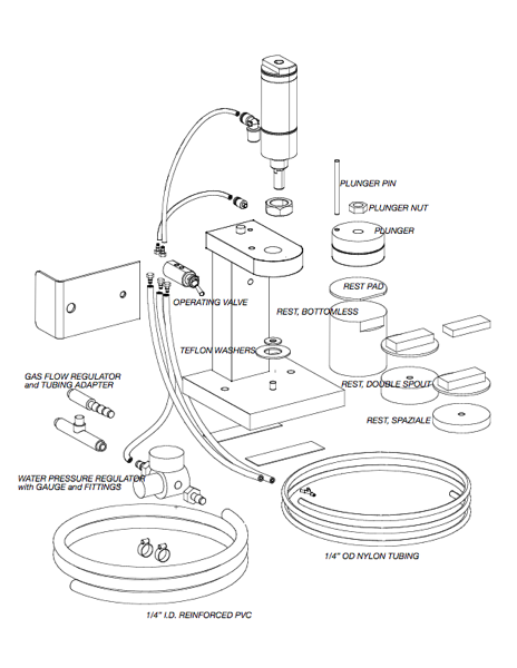
NB: the Water Pressure Regulator with Gauge and fittings shown in the picture is NOT USED with the air/gas PRESS
Questions? Versalab Inc. tel. 505-771-9177 email info@versalab.com